Sunday, November 20, 2022

Logic Gates


Logic gates are the basic building blocks of any digital system. It is an electronic circuit having one or more than one input and only one output. The relationship between the input and the output is based on a certain logic. Based on this, logic gates are named as AND gate, OR gate, NOT gate etc.

AND Gate

A circuit which performs an AND operation is shown in figure. It has n input (n >= 2) and one output.

AND gate

Logic diagram

AND Logical Diagram

Truth Table

AND Truth Table

OR Gate

A circuit which performs an OR operation is shown in figure. It has n input (n >= 2) and one output.

OR gate

Logic diagram

OR Logical Diagram

Truth Table

OR Truth Table

NOT Gate

NOT gate is also known as Inverter. It has one input A and one output Y.

NOT gate

Logic diagram

NOT Logical Diagram

Truth Table

NOT Truth Table

NAND Gate

A NOT-AND operation is known as NAND operation. It has n input (n >= 2) and one output.

NAND gate

Logic diagram

NAND Logical Diagram

Truth Table

NAND Truth Table

NOR Gate

A NOT-OR operation is known as NOR operation. It has n input (n >= 2) and one output.

NOR gate

Logic diagram

NOR Logical Diagram

Truth Table

NOR Truth Table

XOR Gate

XOR or Ex-OR gate is a special type of gate. It can be used in the half adder, full adder and subtractor. The exclusive-OR gate is abbreviated as EX-OR gate or sometime as X-OR gate. It has n input (n >= 2) and one output.

XOR gate

Logic diagram

XOR Logical Diagram

Truth Table

XOR Truth Table

XNOR Gate

XNOR gate is a special type of gate. It can be used in the half adder, full adder and subtractor. The exclusive-NOR gate is abbreviated as EX-NOR gate or sometime as X-NOR gate. It has n input (n >= 2) and one output.

XNOR gate

Logic diagram

XNOR Logical Diagram

Truth Table

XNOR Truth Table

Sunday, November 13, 2022

Boolean Algebra


Boolean Algebra is used to analyze and simplify the digital (logic) circuits. It uses only the binary numbers i.e. 0 and 1. It is also called as Binary Algebraor logical Algebra. Boolean algebra was invented by George Boole in 1854.

Rule in Boolean Algebra

Following are the important rules used in Boolean algebra.

  • Variable used can have only two values. Binary 1 for HIGH and Binary 0 for LOW.

  • Complement of a variable is represented by an overbar (-). Thus, complement of variable B is represented as B Bar. Thus if B = 0 then B Bar= 1 and B = 1 then B Bar = 0.

  • ORing of the variables is represented by a plus (+) sign between them. For example ORing of A, B, C is represented as A + B + C.

  • Logical ANDing of the two or more variable is represented by writing a dot between them such as A.B.C. Sometime the dot may be omitted like ABC.

Boolean Laws

There are six types of Boolean Laws.

Commutative law

Any binary operation which satisfies the following expression is referred to as commutative operation.

Commutative Law

Commutative law states that changing the sequence of the variables does not have any effect on the output of a logic circuit.

Associative law

This law states that the order in which the logic operations are performed is irrelevant as their effect is the same.

Associative Law

Distributive law

Distributive law states the following condition.

Distributive Law

AND law

These laws use the AND operation. Therefore they are called as AND laws.

AND Law

OR law

These laws use the OR operation. Therefore they are called as OR laws.

OR Law

INVERSION law

This law uses the NOT operation. The inversion law states that double inversion of a variable results in the original variable itself.

NOT Law

Important Boolean Theorems

Following are few important boolean Theorems.

Boolean function/theoremsDescription

Boolean Functions

Boolean Functions and Expressions, K-Map and NAND Gates realization

De Morgan's Theorems

De Morgan's Theorem 1 and Theorem 2

Hexadecimal Arithmetic


Hexadecimal Number System

Following are the characteristics of a hexadecimal number system.

  • Uses 10 digits and 6 letters, 0,1,2,3,4,5,6,7,8,9,A,B,C,D,E,F.

  • Letters represents numbers starting from 10. A = 10, B = 11, C = 12, D = 13, E = 14, F = 15.

  • Also called base 16 number system.

  • Each position in a hexadecimal number represents a 0 power of the base (16). Example − 160

  • Last position in a hexadecimal number represents an x power of the base (16). Example − 16x where x represents the last position - 1.

Example

Hexadecimal Number − 19FDE16

Calculating Decimal Equivalent −

StepBinary NumberDecimal Number
Step 119FDE16((1 × 164) + (9 × 163) + (F × 162) + (D × 161) + (E × 160))10
Step 219FDE16((1 × 164) + (9 × 163) + (15 × 162) + (13 × 161) + (14 × 160))10
Step 319FDE16(65536 + 36864 + 3840 + 208 + 14)10
Step 419FDE1610646210

Note − 19FDE16 is normally written as 19FDE.

Hexadecimal Addition

Following hexadecimal addition table will help you greatly to handle Hexadecimal addition.

Hexadecimal Addition Table

To use this table, simply follow the directions used in this example − Add A16and 516. Locate A in the X column then locate the 5 in the Y column. The point in 'sum' area where these two columns intersect is the sum of two numbers.

A16 + 516 = F16. 

Example − Addition

Hexadecimal Addition Example

Hexadecimal Subtraction

The subtraction of hexadecimal numbers follow the same rules as the subtraction of numbers in any other number system. The only variation is in borrowed number. In the decimal system, you borrow a group of 1010. In the binary system, you borrow a group of 210. In the hexadecimal system you borrow a group of 1610.

Example - Subtraction

hexdecimal Substraction Example

Octal Arithmetic


Octal Number System

Following are the characteristics of an octal number system.

  • Uses eight digits, 0,1,2,3,4,5,6,7.

  • Also called base 8 number system.

  • Each position in an octal number represents a 0 power of the base (8). Example: 80

  • Last position in an octal number represents an x power of the base (8). Example: 8x where x represents the last position - 1.

Example

Octal Number − 125708

Calculating Decimal Equivalent −

StepOctal NumberDecimal Number
Step 1125708((1 × 84) + (2 × 83) + (5 × 82) + (7 × 81) + (0 × 80))10
Step 2125708(4096 + 1024 + 320 + 56 + 0)10
Step 3125708549610

Note − 125708 is normally written as 12570.

Octal Addition

Following octal addition table will help you to handle octal addition.

Octal Addition Table

To use this table, simply follow the directions used in this example: Add 68and 58. Locate 6 in the A column then locate the 5 in the B column. The point in 'sum' area where these two columns intersect is the 'sum' of two numbers.

68 + 58 = 138. 

Example − Addition

Octal Addition Example

Octal Subtraction

The subtraction of octal numbers follows the same rules as the subtraction of numbers in any other number system. The only variation is in borrowed number. In the decimal system, you borrow a group of 1010. In the binary system, you borrow a group of 210. In the octal system you borrow a group of 810.

Example − Subtraction

Octal Substraction Example


Binary Arithmetic


Binary arithmetic is essential part of all the digital computers and many other digital system.

Binary Addition

It is a key for binary subtraction, multiplication, division. There are four rules of binary addition.

Addition Table

In fourth case, a binary addition is creating a sum of (1 + 1 = 10) i.e. 0 is written in the given column and a carry of 1 over to the next column.

Example − Addition

Addition Example

Binary Subtraction

Subtraction and Borrow, these two words will be used very frequently for the binary subtraction. There are four rules of binary subtraction.

Subtraction Table

Example − Subtraction

Subtraction Example

Binary Multiplication

Binary multiplication is similar to decimal multiplication. It is simpler than decimal multiplication because only 0s and 1s are involved. There are four rules of binary multiplication.

Multiplication Table

Example − Multiplication

Multiplication Example

Binary Division

Binary division is similar to decimal division. It is called as the long division procedure.

Example − Division

Division Example

Complement Arithmetic


Complements are used in the digital computers in order to simplify the subtraction operation and for the logical manipulations. For each radix-r system (radix r represents base of number system) there are two types of complements.

S.N.ComplementDescription
1Radix ComplementThe radix complement is referred to as the r's complement
2Diminished Radix ComplementThe diminished radix complement is referred to as the (r-1)'s complement

Binary system complements

As the binary system has base r = 2. So the two types of complements for the binary system are 2's complement and 1's complement.

1's complement

The 1's complement of a number is found by changing all 1's to 0's and all 0's to 1's. This is called as taking complement or 1's complement. Example of 1's Complement is as follows.

1's complement

2's complement

The 2's complement of binary number is obtained by adding 1 to the Least Significant Bit (LSB) of 1's complement of the number.

2's complement = 1's complement + 1

Example of 2's Complement is as follows.

2's complement

Sunday, November 6, 2022

Codes Conversion


There are many methods or techniques which can be used to convert code from one format to another. We'll demonstrate here the following

  • Binary to BCD Conversion
  • BCD to Binary Conversion
  • BCD to Excess-3
  • Excess-3 to BCD

Binary to BCD Conversion

Steps

  • Step 1 -- Convert the binary number to decimal.

  • Step 2 -- Convert decimal number to BCD.

Example − convert (11101)2 to BCD.

Step 1 − Convert to Decimal

Binary Number − 111012

Calculating Decimal Equivalent −

StepBinary NumberDecimal Number
Step 1111012((1 × 24) + (1 × 23) + (1 × 22) + (0 × 21) + (1 × 20))10
Step 2111012(16 + 8 + 4 + 0 + 1)10
Step 31110122910

Binary Number − 111012 = Decimal Number − 2910

Step 2 − Convert to BCD

Decimal Number − 2910

Calculating BCD Equivalent. Convert each digit into groups of four binary digits equivalent.

StepDecimal NumberConversion
Step 1291000102 10012
Step 2291000101001BCD

Result

(11101)2 = (00101001)BCD 

BCD to Binary Conversion

Steps

  • Step 1 -- Convert the BCD number to decimal.

  • Step 2 -- Convert decimal to binary.

Example − convert (00101001)BCD to Binary.

Step 1 - Convert to BCD

BCD Number − (00101001)BCD

Calculating Decimal Equivalent. Convert each four digit into a group and get decimal equivalent for each group.

StepBCD NumberConversion
Step 1(00101001)BCD00102 10012
Step 2(00101001)BCD210 910
Step 3(00101001)BCD2910

BCD Number − (00101001)BCD = Decimal Number − 2910

Step 2 - Convert to Binary

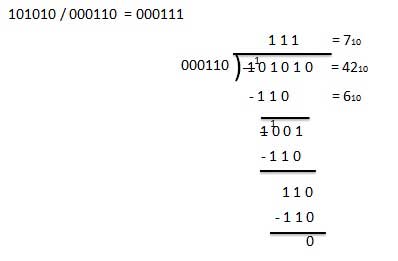
Used long division method for decimal to binary conversion.

Decimal Number − 2910

Calculating Binary Equivalent −

StepOperationResultRemainder
Step 129 / 2141
Step 214 / 270
Step 37 / 231
Step 43 / 211
Step 51 / 201

As mentioned in Steps 2 and 4, the remainders have to be arranged in the reverse order so that the first remainder becomes the least significant digit (LSD) and the last remainder becomes the most significant digit (MSD).

Decimal Number − 2910 = Binary Number − 111012

Result

(00101001)BCD = (11101)2 

BCD to Excess-3

Steps

  • Step 1 -- Convert BCD to decimal.

  • Step 2 -- Add (3)10 to this decimal number.

  • Step 3 -- Convert into binary to get excess-3 code.

Example − convert (1001)BCD to Excess-3.

Step 1 − Convert to decimal

(1001)BCD = 910

Step 2 − Add 3 to decimal

(9)10 + (3)10 = (12)10

Step 3 − Convert to Excess-3

(12)10 = (1100)2

Result

(1001)BCD = (1100)XS-3 

Excess-3 to BCD Conversion

Steps

  • Step 1 -- Subtract (0011)2 from each 4 bit of excess-3 digit to obtain the corresponding BCD code.

Example − convert (10011010)XS-3 to BCD.

Given XS-3 number = 1 0 0 1 1 0 1 0 Subtract (0011)2 = 0 0 1 1 0 0 1 1 -------------------- BCD = 0 1 1 0 0 1 1 1 

Result

(10011010)XS-3 = (01100111)BCD
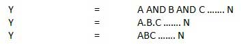
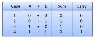
Data Link Layer

In the OSI model, the data link layer is a 4 th  layer from the top and 2 nd  layer from the bottom. The communication channel t...